Subbvofer Monocles
 Preface
I think every meloman of the automobile would want to have an automobile audio system. Let's see how the NFs can be replicated, um, one thought, without saturation. And if the sab is able to collect almost every single one (e.g. on all known 75GDNs or any other NH head) it is much more difficult to deal with. Qualitative, strong enough forcer to be able to unload the sab is costly enough (at least $80 worth of doubtful equipment). So try to help create a fairly qualitative and powerful automobile monobile.
 The booster contains 4 blocks, the power force, the voltage converter, the signal processing unit and the compression and stitching unit. Now they're detailed.
Power force
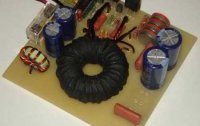
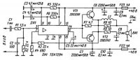
It is based on article A.Chivilch, " Expansion of the power of the microschemist of TDA7294 " , of RADIO No. 11 of 2005. Since the operator was not once tested by me and was marked with sufficient reliability, high output power, quality bass. Power schema below. The original differs only with the replacement of off-duty transistors to more qualitative imports.
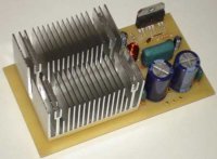
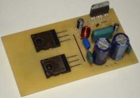
I will not encroach on the principle of the work of the scheme, which can be read in more detail in the original article. I'll just tell you the principled pattern of design. It's packed at 125x70m. All electrolytic condensators other than P-2, pulp, inlet capacity of 1mqf, may be 2.2mqf. 0.25W, though 0.125W. The outlet tranzistors are closed and attached to the fee so that their hulls are parallel to the charge and their thermal dispensation is thermal and through a dielectric film attached to the radiator. I mean, the body of transistors is isolated one from the other and from the radiator. The L1 Induction Cat is incarcerated, wetted wire with a diameter of 1m in two layers and contains 25 turns, an internal diameter of 5mm. The guards are transferred to the stubborn.